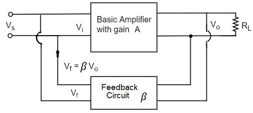
Voltage Shunt Feedback Amplifier Circuit Diagram. The input signal i s is applied as a input i f is the feedback current and v o is the output voltage. In this case both the input and the output are connected in shunt with the feedback circuit.

In this case both the input and the output are connected in shunt with the feedback circuit. When the feedback circuit is allied in shunt through the o p as well as the input then both the o p impedance the i p impedance will be decreased. Derivation of the a circuit and βcircuit for the series shunt feedback amplifier.
In voltage shunt feedback amplifier the feedback signal voltage is given to the base of.
The actual input and output resistances of the feedback amplifier usually exclude rs and. When we say s 51 which means that a i c increases 51 times. Block diagram of voltage shunt negative feedback. But in this case the feedback circuit is connected in shunt with the input.
