Ujt Firing Circuit Diagram. What i mean is that ujts usually have a periodic sequence to them. R1 and r2 are current limiting resistors.
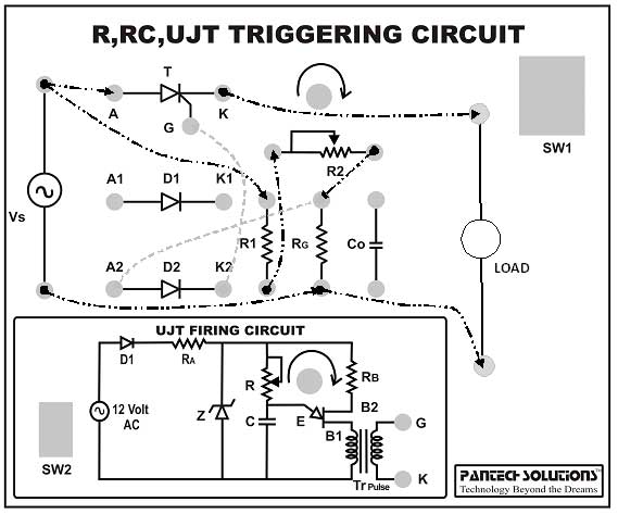
Circuit diagram for ujt triggering circuit. 5ms div voltage y axis. Ac on off switch is provided to control input ac voltage to the power circuit.
Power on off switch is provided to control the input ac mains supply to themodule.
The firing angle control of scr by ujt full wave circuit is shown in the figure a. 5ms div voltage y axis. Observe the waveform for input ac voltage load voltage. Although a unijunction transistor is not a thyristor this device can trigger larger thyristors with a pulse at base b1.
