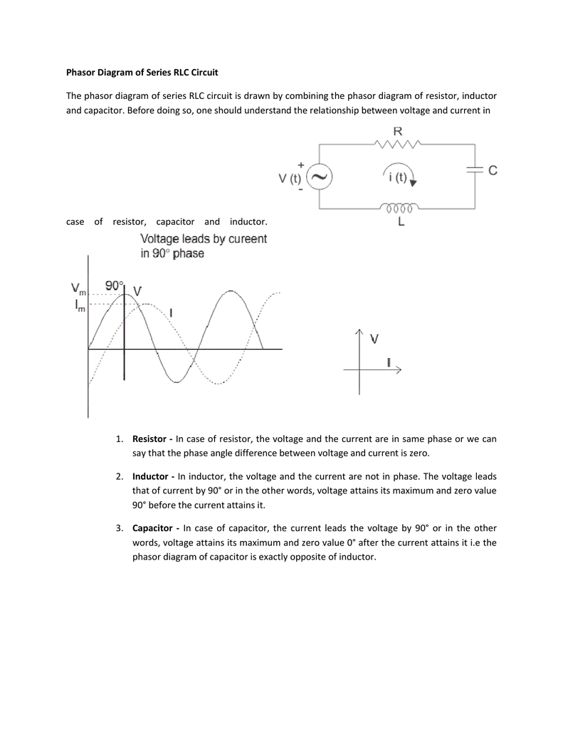
Series Rlc Phasor Diagram Of Lcr Circuit. When the ac voltage is applied through the rlc series circuit the resulting current i flows through the circuit and thus the voltage across each element will be. In case of resistor the voltage and the current are in same phase or we can say that the phase angle difference between voltage and current is zero.

X l 2πfl and x c 1 2πfc. Phasor diagram of series rlc circuit phasor diagram of inductive series rlc circuit. The lcr circuit analysis can be understood better in terms of phasors.
Power in rlc series circuit.
Phasor diagram of series rlc circuit topics discussed 1 phasor diagram of series rlc circuit 2 voltage triangle of series rlc circuit 3 im. An lcr circuit also known as a resonant circuit tuned circuit or an rlc circuit is an electrical circuit consisting of an inductor l capacitor c and resistor r connected in series or parallel. In the rlc series circuit. Impedance triangle of rlc series circuit.
