Series Lcr Circuit Phasor Diagram. In this video phasor diagram representation of voltage and current for series rc rl and rlc circuit has been explained and the examples based on this phaso. Using the phasor diagram derive the expression for the impedance of the circuit.
What Is Rlc Series Circuit Phasor Diagram Impedance Triangle Circuit Globe from circuitglobe.com
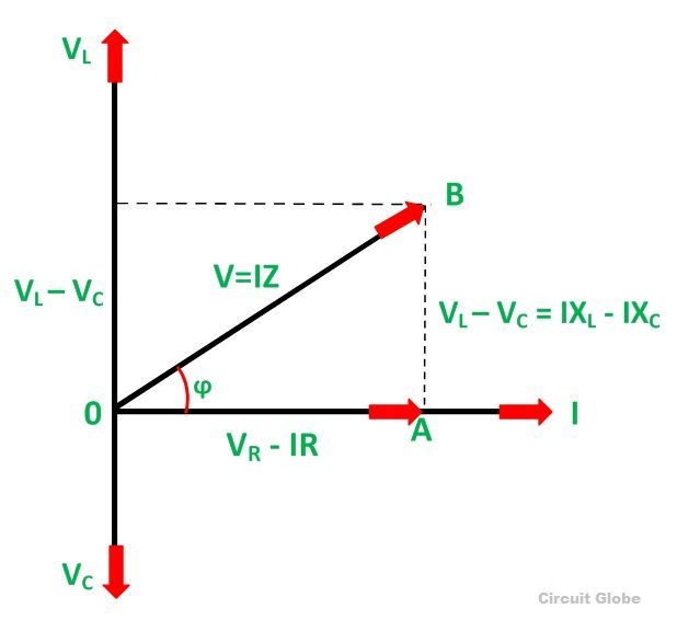
Plot a graph to show the variation of current with frequency of the source explaining the nature of its variation. Draw a plot showing the variation of the current i as a function of angular frequency ω of the applied ac source for the two cases of a series combination of i inductance l 1 capacitance c 1 and resistance r 1 and ii. From the above phasor diagram we know that 1 now current will be equal in all the three as it is a series lcr circuit.
Therefore 2 3 4 using 1 2 3 and 4.
Plot a graph to show the variation of current with frequency of the source explaining the nature of its variation. In this video phasor diagram representation of voltage and current for series rc rl and rlc circuit has been explained and the examples based on this phaso. Using the phasor diagram derive the expression for the impedance of the circuit. From the above phasor diagram we know that 1 now current will be equal in all the three as it is a series lcr circuit.