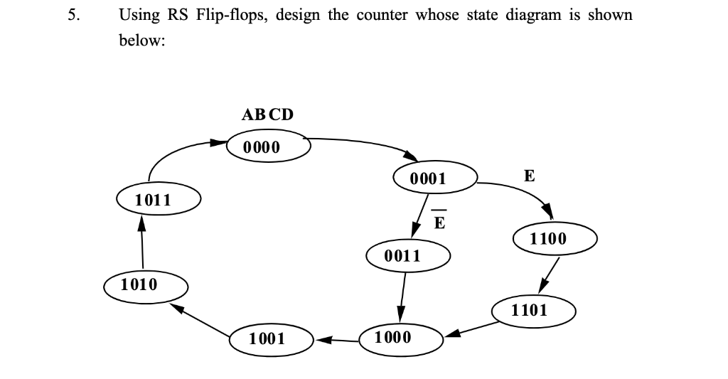
Rs Flip Flop State Diagram. The state table is as shown in table 1 1. The flip flop switches to one state or the other and any one output of the flip flop switches faster than the other.

1 1 state diagram of a 3 bit binary counter solution. Let the three flip flops be a b c. S r flip flop set reset d flip flop delay j k flip flop.
Assign state number for each state 4.
The bistable rs flip flop is activated or set at logic 1 applied to its s input and deactivated or reset by a logic 1 applied to r. Characteristic equation q next d d flip flop symbol characteristictable. Let the three flip flops be a b c. Draw a state diagram 3.
