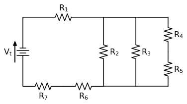
Resistor Network Schematic. Never mix the two different symbols within the same schematic. Some complex networks of resistors cannot be resolved in this manner requiring more sophisticated circuit analysis.

A resistor network that is a combination of parallel and series connections can be broken up into smaller parts that are either one or the other. For resistors in parallel the equivalent circuit resistance r t is calculated differently. To exit place part mode r mb end mode or press escape.
An rc circuit also known as an rc filter or rc network stands for a resistor capacitor circuit.
Strategy for simplifying a resistor network begin as far away as possible from the circuit location in question. When you place the first resistor in the schematic another resistor will be attached to the cursor click on the right mouse button rmb rotate or press r on the keyboard and place the second resistor. An rc circuit is defined as an electrical circuit composed of the passive circuit components of a resistor r and capacitor c driven by a voltage source or current source. The eight individual resistors each have a node that only connectors to one pin of the device with no resistors connected to any other resistor in the package.
