Rc High Pass Filter Transfer Function. The complex impedance of a capacitor is given as zc 1 sc. The passive rc high pass filter circuit connected to the non inverting terminal of the unity gain operational amplifier is shown below.
Formula rc high pass filter calculation. The response of the filter is displayed on graphs showing bode diagram nyquist diagram impulse response and step response. The circuit diagram of high pass and low pass filter is the same just interchange the capacitor and resistor.
Formula rc high pass filter calculation.
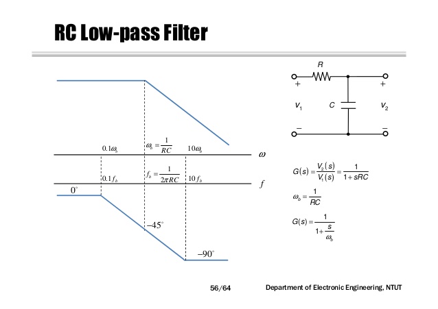
The complex impedance of a capacitor is given as zc 1 sc. A low pass filter lpf is a filter that passes signals with a frequency lower than a selected cutoff frequency and attenuates signals with frequencies higher than the cutoff frequency. The simple first order electronic high pass filter shown in figure 1 is implemented by placing an input voltage across the series combination of a capacitor and a resistor and using the voltage across the resistor as an output. If you cascade two identical rc low pass filters the overall transfer function corresponds to a second order response but the q factor is always 0 5.
