Rankine Cycle Ts Diagram Explanation. In these turbines the high pressure stage receives steam this steam is nearly saturated steam x 0 995 point c at the figure. 1 2 3 isobaric heat transfer.
On this channel you can get education and knowledge for general issues and topics. When plotted on a pressure volume diagram the isobaric processes follow the isobaric lines for the gas the horizontal lines adiabatic processes move between these horizontal lines and the area bounded by the complete cycle path represents the total work that can be done during one cycle. 275 6 c from a steam generator and exhaust it to moisture separator reheater point d.
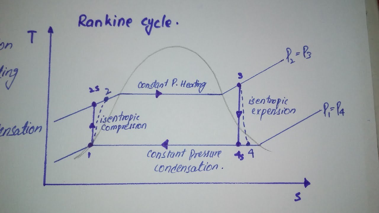
The rankine cycle is a modified form of carnot cycle in which the isothermal compression 3 4 is continued unit the steam is condensed into water.
The rankine cycle operates in the following steps. The ts diagram shows us that the reheat rankine cycle combines all of the advantages of of the superheat method with the simple method of increasing the boiler pressure and decreasing the condenser pressure. The rankine cycle is often plotted on a pressure volume diagram pv diagram and on a temperature entropy diagram ts diagram. 275 6 c from a steam generator and exhaust it to moisture separator reheater point d.
