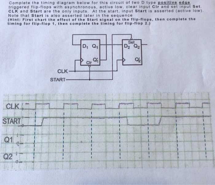
Positive D Flip Flop Timing Diagram. Cse370 lecture 14 5 behavior is the same unless input changes while the clock is high clk d q ff q latch latches versus flip flops d q q clk d q q clk. J corresponds to a set signal and k corresponds to a reset signal.

At the triggering edge. This is known as a timing diagram for a jk flip flop. Just before pulse c the d input goes low so at the positive going edge of pulse c q goes low.
The enable signal is renamed to be the clock.
About press copyright contact us creators advertise developers terms privacy policy safety how youtube works test new features press copyright contact us creators. At the triggering edge. Just before pulse c the d input goes low so at the positive going edge of pulse c q goes low. Only the value of d at the positive edge matters.
