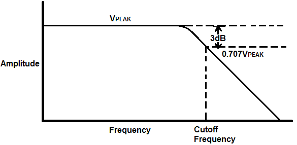
Passive Low Pass Filter Graph. In this tutorial we will learn about passive low pass rc filters. The most convenient means of evaluating a filter s effect on a signal is to examine a plot of the filter s frequency response.

In the following sections you can learn about the basic circuit of passive low pass rc filters its frequency response output voltage applications and many more. These graphs often called bode plots have magnitude in decibels on the vertical axis and frequency on the horizontal axis. This is the 6th tutorial of proteus series still if you don t know how to pick components or any other basic thing then watch from the first tutorial in this.
Order passive rc low pass filteri figure 3.
As the name suggests it is a low pass filter designed using passive components. Please notify the admin if there are any bugs or requests. This is the 6th tutorial of proteus series still if you don t know how to pick components or any other basic thing then watch from the first tutorial in this. The graph is unable to plot below 1hz at the moment.
