P55 Mosfet Inverter Circuit Diagram. The diagram above shows the entire design of the proposed spwm inverter circuit using ic 555 where the center ic 555 and the associated bjt mosfet stages forms a basic square wave inverter circuit. P55 mosfet which is used in inverter fab32q2 three phase inverter mosfet diagram smps diagram schematics smps inverter circuit 3 phase mosfet inverter motor inverter pcb board circuit diagram thyristor inverter schematics 1n4148 do214ac.
Three phase inverters require microcontroller design where the timings of the all three phases need to be precisely timed and executed. The diagram above shows the entire design of the proposed spwm inverter circuit using ic 555 where the center ic 555 and the associated bjt mosfet stages forms a basic square wave inverter circuit. It can be used to power lamps up to 35w but can be made to drive more powerful loads by adding more mosfets.
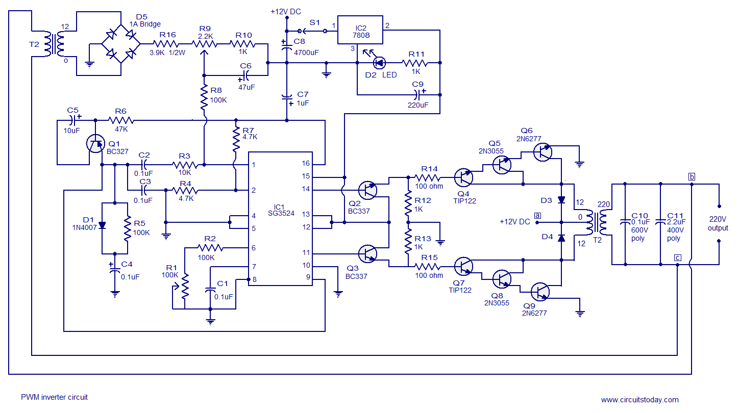
Simple 12v to 230vac inverter circuit.
Download a better high resolution circuit diagram here. I experiment it to work well. Circuit diagram of inverter. A 12v dc to 220 v ac converter can also be designed using simple transistors.
