Non Inverting Op Amp Circuit Analysis. Therefore the outputs of the two non inverters in the first stage of the instrumentation amplifier are. The voltage follower or unity gain buffer is a special and very useful type of non inverting amplifier circuit that is commonly used in electronics to isolated circuits from each other especially in high order state variable or sallen key type active filters to separate one filter stage from the other.
One of the most important signal processing applications of op amps is to make weak signals louder and bigger. Typical digital buffer ic s available are the 74ls125 quad 3 state buffer or the more common 74ls244 octal buffer. While this is useful in certain applications there are many where you want more gain.
Those extra resistors are used to set the gain of the op amp stage.
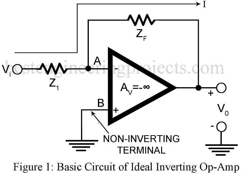
The subtracting feature is evident from the circuit configuration which shows that one input signal is applied to the inverting terminal and the other to the non inverting terminal. Simple non inverting amplifier the non inverting amplifier is the easiest to analyze and is shown in figure 1 below. The resulting circuit is called the instrumentation amplifier. Recall that the output resistance of a non inverting amplifier is very low its output voltage will not affected by the load circuit here the differential amplifier whose its input resistance and is not very high.
