Loop Power Indicator Circuit Diagram. A switch loop single pole switches light dimmer and a few choices for wiring a outlet switch combo device. This is possible because current is the same throughout the loop so voltage drops caused by loop powered devices do not affect the current signal.
How To Make 4 20 Ma Current Loop Measurements from www.dataq.com
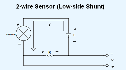
Power was instead used in the loop the magnitude of current would be continuously changing making it difficult to discern the signal level being transmitted. This is provided by the power supply with the voltage of the supply labeled as vtot. A current loop requires voltage to drive the current.
This is provided by the power supply with the voltage of the supply labeled as vtot.
Current then flows through the loop passing through each load. A switch loop single pole switches light dimmer and a few choices for wiring a outlet switch combo device. The voltage drop at each load can be calculated from ohm s. Part two the fundamentals of loop powered devices explored how two wire or loop powered devices receive their power from the 4 20 ma process signal loop connected to the device.