Jk Flip Flop Timing Diagram Explanation. The jk flip flop has two inputs labeled j and k. If j is 1 and k is 0 q is 1.
At the triggering edge. Below snapshot shows it. Timing diagram of a master flip flop when the clock pulse is high the output of master is high and remains high till the clock is low because the state is stored.
Timing diagram of a master flip flop when the clock pulse is high the output of master is high and remains high till the clock is low because the state is stored.
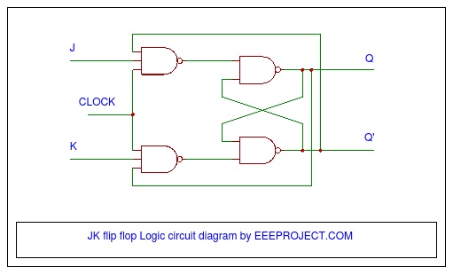
Symbol for the jk flip flop. The old two input and gates of the s r flip flop have been replaced with 3 input and gates and the third input of each gate receives feedback from the q and q outputs. Jk flip flop circuit diagram and explanation. The jk flip flop is basically a gated rs flip flop with the addition of the clock input circuitry.
