Jk Flip Flop Block Diagram And Truth Table. Jk flip flop circuit diagram and explanation. Sr flip flops are used in control circuits.
In addition to the basic input output pins shown in figure 1 j k flip flops can also have special inputs like clear clr and preset pr figure 4. Jk flip flop circuit diagram. Jk flip flop construction logic circuit diagram logic symbol truth table characteristic equation excitation table are discussed.
In addition to the basic input output pins shown in figure 1 j k flip flops can also have special inputs like clear clr and preset pr figure 4.
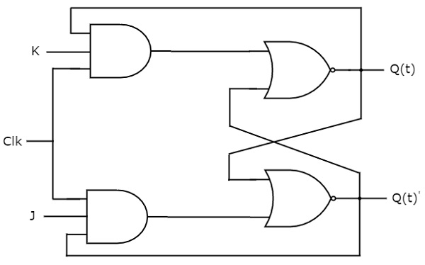
T flip flops are similar to jk flip flops. The two input and gates of the rs flip flop is replaced by the two 3 inputs nand gates with the third input of each gate connected to the outputs at q and ǭ. T flip flops are similar to jk flip flops. Here j s and k r.
