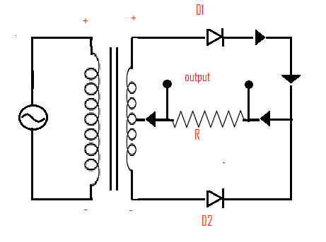
Half Wave Rectifier Diagram Ncert. Given below is the half wave rectifier diagram. Transformer with primary and secondary coils.

Load resistance r l. As you know a diode is to electric current like a one way valve is to water it allows electric current to flow in only one direction. And a diode works and allows current in only one direction and blocks it in another one.
The obtained secondary low voltage is applied to the diode.
During the positive cycle of the input alternating voltage the diode is forward biased and conducts current. The output is measured across the load resistance r l. A half wave rectifier circuit diagram looks like this. A c input will be obtained as d c output.
