Full Subtractor Logic Diagram Using Basic Gates. This circuit has three inputs and two outputs the three inputs a b and bin denote the minuend subtrahend and previous borrow respectively. Truth table of full subtractor.
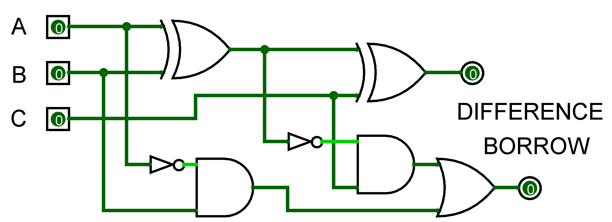
In the circuit diagram you can see the full subtractor circuit consist of two half adder and an or gate. To develop digital circuit building and troubleshooting skills. Fig 3 logic diagram for fs.
Truth table of full subtractor.
Full subtractor circuit diagram using basic gates and applications march 7 2020 by watelectronics full subtractor and the half subtractor both belong to the family of digital electronics. It also takes into consideration borrow of the lower significant stage. Logic diagram of half subtractor. Fig 3 logic diagram for fs.
