Full Subtractor Circuit Diagram Using Nand Gate. Fs can be implemented by a combination of one 3 8 decoder and two or gate. It also takes into consideration borrow of the lower significant stage.
Fs can be implemented by a combination of one 3 8 decoder and two or gate. The full subtractor is a combination of x or and or not gates. Display result at system seven segment.
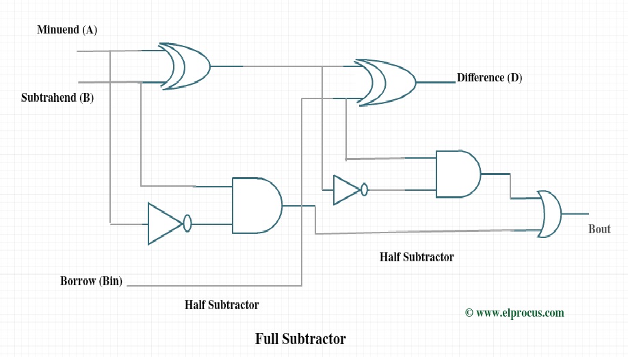
Full subtractor contains 3 inputs and 2 outputs difference.
In a full subtractor the logic circuit should have three inputs and two outputs. A nand gate is made using transistors and junction diodes. Adder in digital logic. Realizing full subtractor using nand gates only part 1 contribute.
