Draw A 4 Bit Adder Subtractor Circuit. We will need to discuss an example to understand this in more details. Add two binary numbers 7 and 15 with previous carry 0.
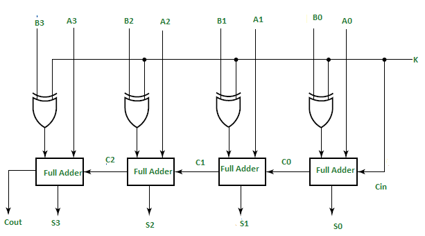
The circuit has a mode input bit m that controls its operation. A parallel adder is an arithmetic combinational logic circuit that is used to add more than one bit of data simultaneously. This will be followed by other two full adders and thus the final sum is c4s3s2s1s0.
Lets consider two 4 bit binary numbers a and b as inputs to the digital circuit for the operation with digits.
Next block should be full adder as there are three inputs applied to it. We will need to discuss an example to understand this in more details. Implement the 4 bit binary adder subtractor logic circuit on proteus simulation program. In this example we will use some terms from register transfer level rtl implementations.
