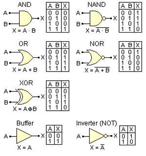
Diode Transistor Logic Truth Table. In the diode or gate when both input a and b 0v or low then both diodes d1 and d2 are off state because of reverse biasing. Only if all inputs a and b and c are 0 will the output be 0.

In the diode or gate when both input a and b 0v or low then both diodes d1 and d2 are off state because of reverse biasing. Write the truth table for the input combinations of 0 v and 5 v with respect to the ground. So no current pass through r and no voltage drop will occur.
Positive nor gate may be implemented by putting transistor not gate at the output of a diode or gate as shown in figure 3.
Figure 2 truth table of and gate. Implementation of nor gate. So no current pass through r and no voltage drop will occur. Figure 3 a gives the circuit symbol and boolean expression for nor gate while figure 1 b gives the two input truth table.
