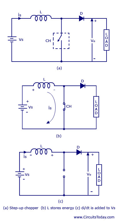
Class C Chopper Circuit Diagram. Essentially a chopper is an electronic switch that is used to interrupt one signal under the control of another. No lengthy explanation required da choppers.

Type d chopper or two quadrant type b chopper two quadrant type b chopper or d chopper circuit. Essentially a chopper is an electronic switch that is used to interrupt one signal under the control of another. The circuit diagram of the type d chopper is shown in the above figure.
In fact class c or type c chopper is obtained by the parallel connection of class a and class b chopper.
When v 0 v s the two choppers will be off but both the diodes d1 and d2 will start conducting. Q 3 a class c chopper circuit is shown in the figure. When v 0 v s the two choppers will be off but both the diodes d1 and d2 will start conducting. The load is 20w.
