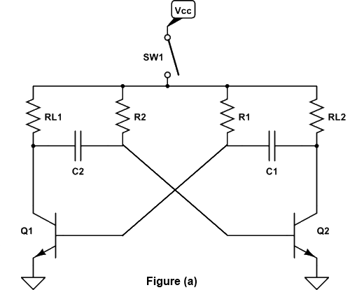
Bistable Multivibrator Using Bjt. The basic bipolar transistor bjt version of an astable multivibrator as shown in fig. A multivibrator circuit consists generally of two inverting amplifier stages.

Operation of bistable multivibrator. The following figure shows the circuit diagram of a self biased bistable multivibrator. This is a stable state of the bistable.
4 1 1 has two outputs that repeatedly change state at a rate determined by the time constants of its feedback network.
The two amplifiers are connected in series or cascade and a feedback path connects from the output of the second amplifier back to the input of the first. In the bistable multivibrator both coupling paths are dc coupled. This is a stable state of the bistable. When the circuit is switched on due to some circuit imbalances as in astable one of the transistors say q 1 gets switched on while the transistor q 2 gets switched off.
