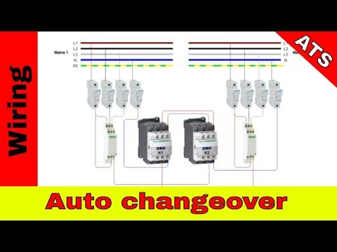
Automatic Changeover Switch Control Circuit Diagram. A contactor when closed opens its own auxiliary contact. This circuit is based on the principle of bistable mode operation of 555 timer.
Good evening boss i read about automatic change over few days ago and they. The circuit diagram shown here is of a automatic changeover switch using ic ltc4412 from linear technologies. Typical automatic transfer switch diagrams technical information.
Automatic changeover switch circuit principle.
This circuit can be used for the automatic switchover of a load between a battery and a wall adapter ltc4412 controls an external p channel mosfet to create a near ideal diode function for power switch over and load sharing. In fig 2 different connection and wiring diagrams are shown for a two pole single phase manual changeover switch. This circuit can be used for the automatic switchover of a load between a battery and a wall adapter ltc4412 controls an external p channel mosfet to create a near ideal diode function for power switch over and load sharing. In this mode the timer output is either high or low depending upon the status of trigger and reset pin.
