Astable Multivibrator Using Transistor Graph. With no external signal applied the transistors alternately switch from cutoff to saturation state at a frequency determined by the rc time constants of the coupling circuits. The led on the right side is lit when the transistor on the right side q2 is on.
Power supply transistors resistors capacitors connection wire and bread board. When a transistor is on its collector and emitter act as a short circuit. In the above diagram we can find two transistors which is wired as a switch.
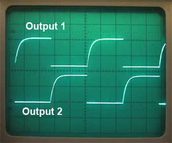
The classical 2 transistor astable multivibrator is the following circuit.
Please do read the article transistor as a switch. To me i can see what kind of multivibrator is being used in some science displays in some museums in jakarta. In the above diagram we can find two transistors which is wired as a switch. An astable multivibrator circuit diagram with 2 leds.
