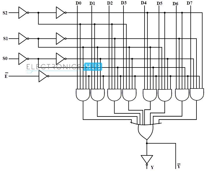
8x1 Mux Circuit. 8x1 mux logic diagram. The two outputs are active low and active high outputs.

Mux is a device that has 2 n input lines. You may verify other combinations of select lines from the truth table. This abruptly reduces the number of logic gates or integrated circuits to perform the logic function since the multiplexer is a single integrated circuit.
This abruptly reduces the number of logic gates or integrated circuits to perform the logic function since the multiplexer is a single integrated circuit.
The two 4 to 1 multiplexer outputs are fed into the 2 to 1 with the selector pins on the 4 to 1 s put in parallel giving a total number of selector inputs to 3 which is equivalent to an 8 to 1. The two 4 to 1 multiplexer outputs are fed into the 2 to 1 with the selector pins on the 4 to 1 s put in parallel giving a total number of selector inputs to 3 which is equivalent to an 8 to 1. 8x1 mux logic diagram. Whereas 16x1 multiplexer has 16 data inputs 4 selection lines and one output.
