4 To 1 Multiplexer With Enable Truth Table. Block diagram and truth table for dual 4 to 1 multiplexer. On the basis of the combination of inputs that are present at the selection lines s 0 and s 1 one of these 4 inputs are connected to the output.
On the basis of the truth table of the 4 1 mux we can write the equation of the multiplexer. We have already discussed the possible cases of combination of binary values which gives the desired input. That means when s1 0 and s0 0 the output at y is d0 similarly y is d1 if the select inputs s1 0 and s0 1 and so on.
The input data lines a b c d are selected depending on the values of the select lines.
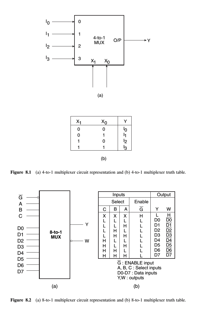
The truth table of a 4 to 1 multiplexer is shown below in which four input combinations 00 10 01 and 11 on the select lines respectively switches the inputs d0 d2 d1 and d3 to the output. 4 to 1 multiplexer. Design truth table logical expression circuit diagram for it. The truth table of a 4 to 1 multiplexer is shown below in which four input combinations 00 10 01 and 11 on the select lines respectively switches the inputs d0 d2 d1 and d3 to the output.
