4 Bit Priority Encoder Circuit Diagram. Let s write the truth table for a 4 2. They are often used to control interrupt requests by acting on the highest priority interrupt input.
8 to 3 priority encoder or octal to binary priority encoder. The truth table of an octal to binary priority encoder is shown below. For example if i7 i6 and i0 bits of an 8 bit input are high then the output 111 will be for i7.
In this truth table for all the non explicitly defined input combinations i e.
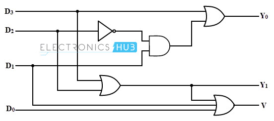
The circuit diagram of 4 to 2 priority encoder is shown in the following figure. A1 a0 here the input y3 has the highest priority whereas the input y0 has the lowest priority in this case even if more than one input is 1 at the same time the output will be the binary code corresponding to the input which is having higher priority. An n bit binary encoder has 2 n input lines and n bit output lines with common types that include 4 to 2 8 to 3 and 16 to 4 line configurations. Y3 y2 y1 y0 and 2 outputs.
